
The original schematic design will be known as Default Variant and will contain all the components and connections.Each variant will be a spin-off of the original design. An example of a variant would be some components which should not be populated on the PCB as per working conditions.
Follow the steps below for more understanding.
If you need default variant without any changes kindly jump to Section A.
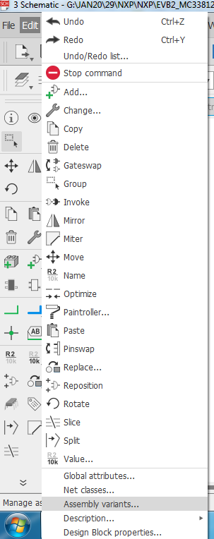
go to Edit >> Assembly variants...
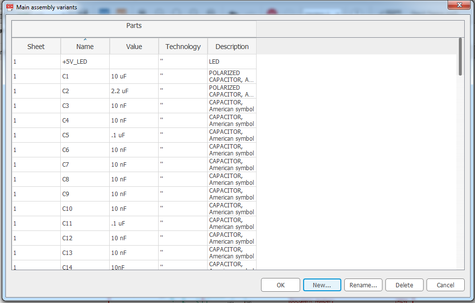
A dialog box appears which is your default variant. It will appear with four column listings: Component Name, Value, Technology and Description.
To create a new variant click NEW as shown below
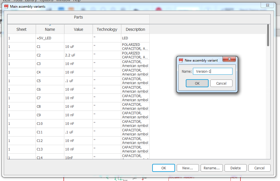
A dialog box appears for naming your variant. A new set of columns will appear in the variant where Visibility, Value and Technology can be changed.
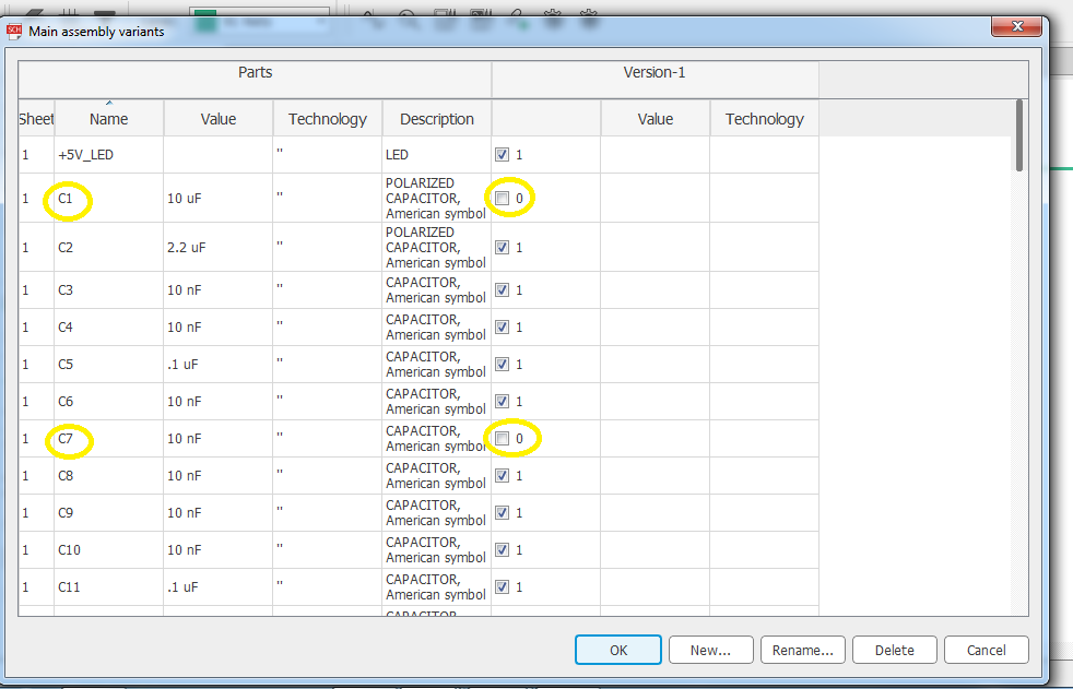
The first column that appears for the assembly variant is Visibility.
The remaining columns are Value and Technology. In this example we will disable the visibility of components that should not be populated. In our case it is C1 and C7.
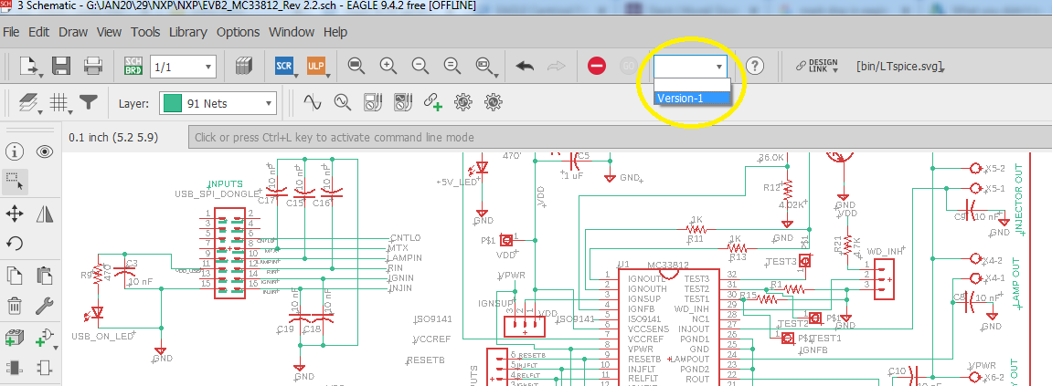
No changes will occur in the schematic. You need to change the variant to see the changes.For this click on the Variant Dropdown menu that appears on top tool bar and select the desired variant.
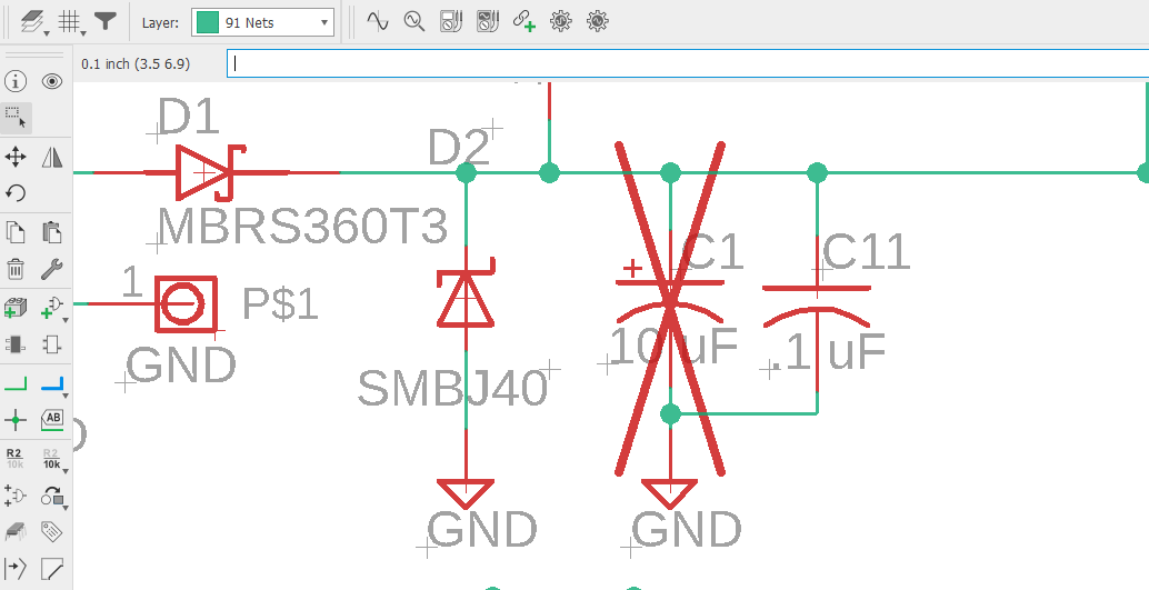
After selecting the new variant you will see the changes applied to the schematic design.
The Cross mark that appears on C1 indicates that this component should not be populated on the board.
Now while exporting BOM for the new variant the components C1 and C7 will be ignored.
Note : Assembly variant changes can only be performed in Eagle Schematic Editor
Section A
1) To generate the BOM file make sure you are in EAGLE Schematic Editor.
go to File>>Export>>BOM
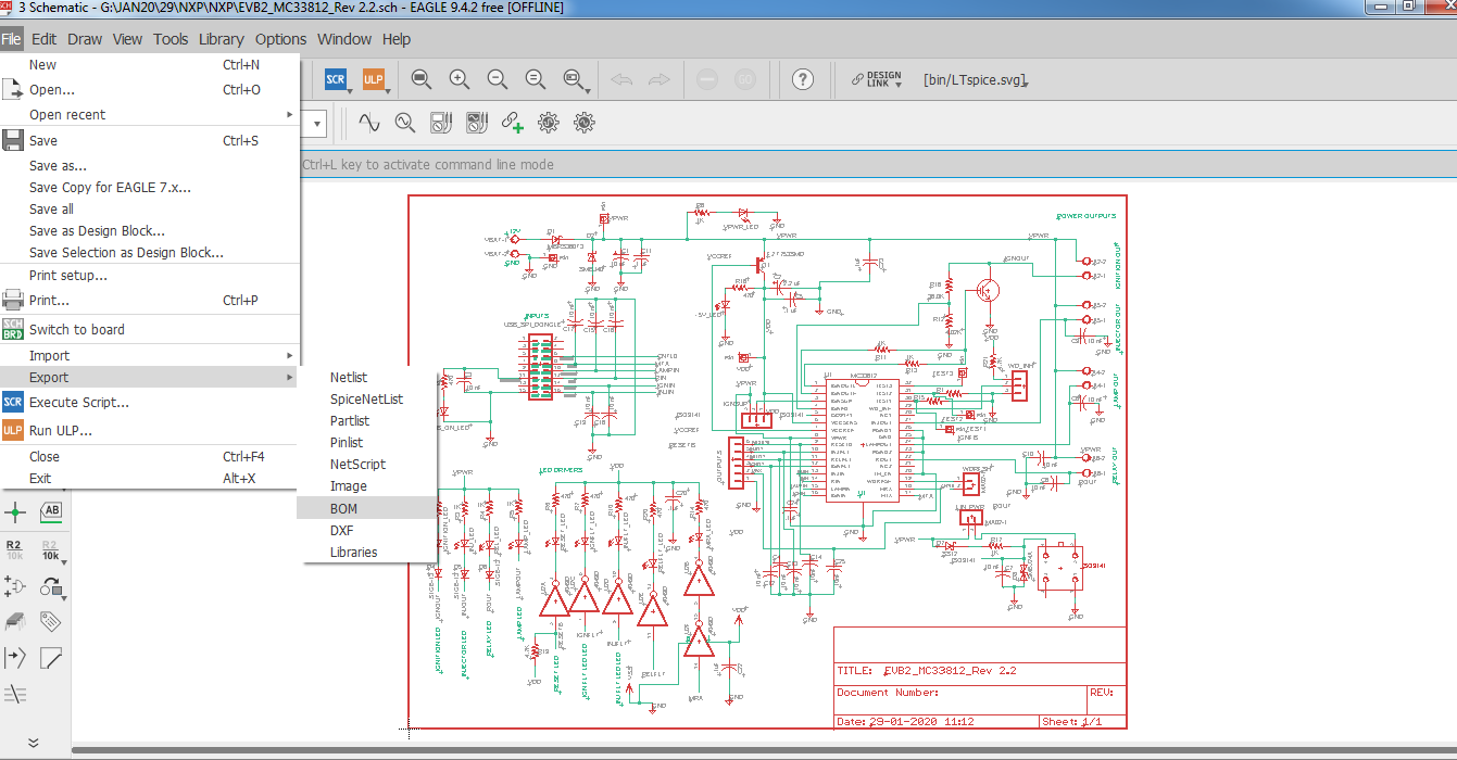
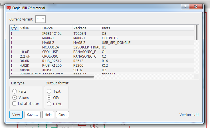
2) This will open up new window which shows the BOM configurations.
Check the Values and the CSV option.
Uncheck List attributes and save the file in desired location by clicking Save option.
3) The saved file needs to be edited before uploading to Lion Circuits.Kindly import the saved csv file into any spreadsheet editor. In this example we are using Google Docs.
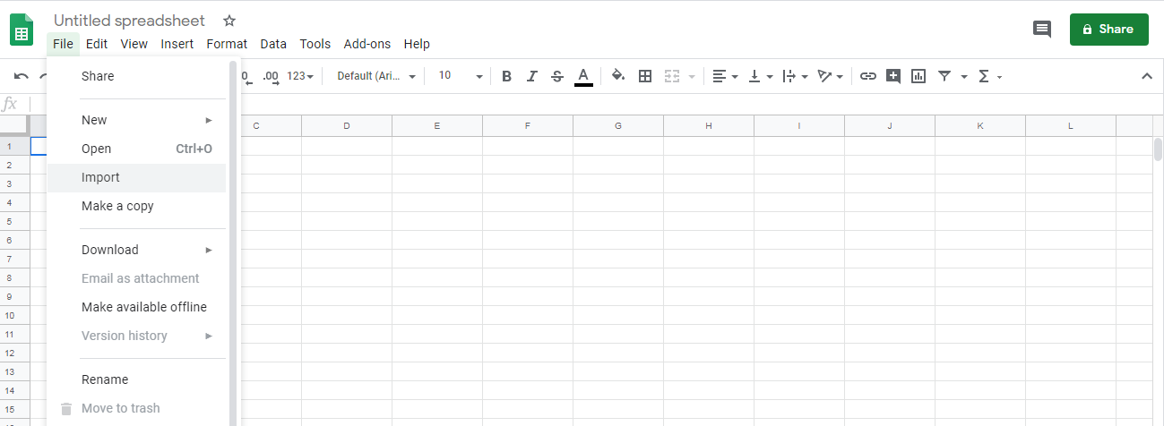
go to File >> Import. In the newly opened window select upload and select the recently created Bom.csv file.
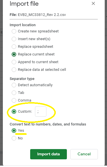
4) Now you can configure how to import file. You need to put in the correct separator which in our case is semicolon ' ; ' and click import data.
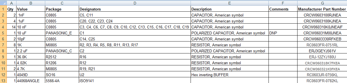
5) Now you need to adjust the file by changing column names, addition/deletion of columns so that it matches what is shown below
Here is the step by step Order Guide

